| Pump Model | EMC - Two Stage Pump(Capacity and Pressure) |
| Pump Rating | 1500gpm @ 150psi |
| Pump Performance | 1505gpm @ 150psi in Capacity 1052gpm @ 200psi in Capacity 756gpm @ 250psi in Pressure |
| *Pump is "Pressure" unless exceeding 70% of the
pumps rated capacity(1050gpm). **Pump rated while drafting with a 10’ lift. |
|
| Water Tank | 500 gallons |
| Foam Tank | 30 gallons Class "A" Foam Concentrate |
| Air Compressor | 120cfm at 150psi |
The governor system monitors pump pressure and varies engine speed to maintain a user selected pump pressure. It acts as the pump panel throttle control and eliminates the need for a discharge relief valve. If the pump discharge pressure exceeds the selected pressure, the governor will instantaneously throttle back the engine to reduce output pressure. likewise, If the discharge pressure is too low, the governor will throttle up to maintain the desired pressure.
The Electronic Fire Commander(EFC) operates the Pressure Sensor Governor(PSG) and displays all vital engine operating parameters such as engine temperature, oil pressure, engine rpm, and voltage. It also notifies the driver of any problems with the engine and apparatus through the information center’s alpha/numeric display.
How does it work? A pressure transducer up to 400psi is installed in the water discharge manifold of the pump. The transducer continuously monitors pump pressure sending a signal to the Electronic Control Module(ECM), which modulates fueling in order to maintain a set pump pressure, regardless of the pump flow rate or engine speed(within engine operating capabilities).
To operate, engage pump, press "MODE" to the "PRESSURE" setting, then increase to the desired discharge pressure. To shut the system down, decrease rpm to idle speed before disengaging the pump.
A pump cavitation protection feature is built in to the EFC, which will return the engine to idle should the pump cavitate. Cavitation is sensed by a pump discharge pressure less than 30psi, and engine speed above 200rpm for greater than 5 seconds.
Located on the intake side of the pump. Protects the pump from high pressure surges coming into the pump. On E13, the relief is set all the way open to automatically dump water onto the ground when the hydrant is charged. The valve is then closed down to the point that the valve no longer dumps water at that hydrants normal operating pressure. It protects supply lines, the pump, hydrants, and water mains from harmful back pressure surges.
The Darley electric motor rotary vane primer will develop up to 25in Hg in an air tight system. The primer is activated by a combination spring return on/off valve and electric switch. Pulling the valve out opens the valve and closes the electrical circuit to start the motor. Pull the primer shutoff valve all the way out to start priming, and hold open until water discharges from the primer exhaust port. Push the valve all the way in to shut off primer motor and seal tight.
The rotary vane pump is constructed with moveable elements that automatically compensate for wear and maintain a tighter fit with closer clearances as the pump is used. In this type of pump, the rotor is mounted off-center inside the housing. The distance between the rotor and the housing is much greater at the intake than at the discharge. The vanes are free to move within the slots where they are mounted. As the rotor turns, the vanes are forced against the housing by centrifugal force. When the surface of the vanes that is in contact with the housing becomes worn, the centrifugal force causes it to extend further, thus automatically maintaining the tight fit. This self-adjusting feature makes the rotary vane pump much more efficient at pumping air than the standard rotary gear pump.
As the rotor turns, air is trapped between the rotor and the casing in the pockets formed by the adjacent vanes. As the vanes turn, the pockets become smaller, which compresses the air and causes pressure to build up. This pocket becomes even smaller as the vanes progress towards the discharge opening. At this point, the pressure reaches its maximum level, forcing the trapped air out of the pump. The air/water is prevented from returning to the intake by the close spacing of the rotor at that point. The air being evacuated from the intake side causes a reduced pressure and water is forced into the pump by atmospheric pressure until the pump fills with water. At this point, the pump is primed and will force water out of the discharge in the same manner that the air was forced out.
E13 has an air actuated transfer valve with a panel mounted control that controls the transfer from parallel(volume) to series(pressure). Colored indicator lights are associated with the switch to provide an indicator of the position of the transfer valve. The valve should not be switched unless pump discharge pressure is less than 50psi. Regardless of the valve setting, both impellers spin at the same rate.
In series, or pressure mode, water enters the pump and the transfer valve direct the flow of water from the first stage impeller to the second stage impeller so the each impeller applies pressure to the same water , dividing the pressure increase between the two impellers. I.E.The first impeller puts 100psi out, the second impeller takes that 100psi and adds 100psi to it giving a final discharge pressure of 200psi.
In parallel, or volume mode, the transfer valve directs water into both impellers at once, and both impellers put out the same discharge pressure.
The pump should be run in pressure at all time s except when exceeding half of the pumps rated capacity at draft(750gpm) or 70% of the capacity when hooked to a hydrant(1050gpm). The main benefit of the transfer valve is the reduced engine strain from running at lower rpms.
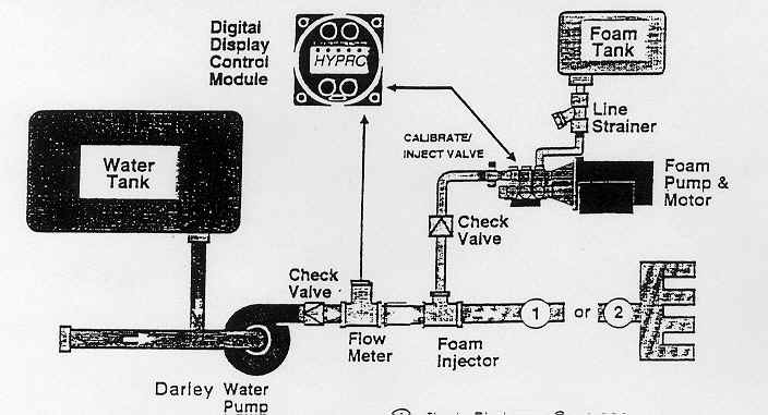
E13 is equipped with a Foam Pro 2002 automatic, electronic, discharge side foam proportioning system. The foam proportioner is a built in, fully self-contained, flow meter based, direct injection system. There are five basic units that make up the system. They are: injection pump, motor, paddle wheel type flowmeter, injection fitting, and the panel mounted, digital, push button, control module unit. The foam percentage to water ratio is adjustable from 0.1% to 9.9% in .1% increments.
The unit operates by sensing water flow. The paddle wheel flowmeter then sends a signal to the control unit displaying this flow. If the unit is turned on, the microprocessor control sends a signal to the injector motor to begin injecting foam concentrate into the plumbing based on the percentage set at the control module.
| Foam Pump | Hydro Plunger Pump |
| Foam Output | 5.0gpm @ 150psi |
| Pump Motor | 3/4hp 12 volt DC |
| Maximum Operating Pressure | 400psi |
| Maximum Operating Temperature | 160deg F |
| Maximum Amp Draw | 56amps |
System Capacity |
|
Foam Concentration |
Water Flow |
0.3% |
1666gpm |
3.0% |
166gpm |
6.0% |
83gpm |
The minimum amount of foam solution that must be applied to a fire, per minute, per square foot of a fire.
This method of foam application may be employed when an elevated object is near or within the area of the burning pool of liquid. The object may be a wall, tank shell or similar structure.The foam stream is directed off of the object, allowing the foam stream to run down onto the surface of the fuel.
Foam specially designed for use on Class A combustibles. Class A foams are essentially wetting agents that reduce the surface tension of water and allow it to soak into combustible materials more easily.
Portable proportioning device that injects a liquid, such as foam concentrate, into water flowing through a hoseline.
Extinguishing agent formed by mixing a foam concentrate with water and aerating the solution for expansion; for use on Class A and Class B fires. Foam may be protein, synthetic, aqueous film forming, high expansion, or alcohol type. Also know as finished foam.
The raw foam liquid as it rests in its storage container prior to the introduction of water and air.
Device that injects the correct amount of foam concentrate into the water stream to make a foam solution.
Mixture of foam solution and water after it leaves the foam proportioner, but before it is discharged from the nozzle and air is added to it.
Organic compound containing only hydrogen and carbon and found primarily in petroleum products and coal.
Foams produced by a physical agitation of a mixture of water, air and a foaming agent.
Flammable liquids that have an attraction for water, much like a positive magnetic pole attracts a negative pole; examples include alcohol’s, ketones, and lacquers.
This method of foam application direct the stream into the air above the fire and allows the foam to float gently down onto the surface of the fuel.
This method of foam application direct the foam stream on the ground near the front edge of the liquid pool on fire. The foam then rolls across the surface of the fuel.
When fluid is forced under pressure through a restricted orifice, there is a decrease in the pressure exerted against the side of the constriction and a corresponding and corresponding increase in the velocity of the fluid. Because the surrounding air is under greater pressure, it rushes into the area of lower pressure.
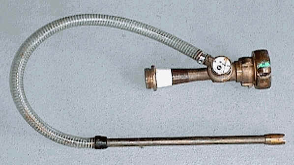
The purpose of a foam eductor is to add foam concentrate to a water stream at a desired rate in order to produce a foam solution. The foam eductor works on the Venturi principle. Water enters the foam eductor through a 1 1/2" opening at 200 psi. The opening is then tapered down, which causes the velocity of the water to increase. This increase in velocity causes a low pressure area to form above the metering orifice which is connected to the pick up tube. When the pick up tube is placed into a bucket of foam concentrate, atmospheric pressure pushes the concentrate into the pickup tube, and then into the low pressure area where it is mixed with the water stream. The rate(percentage) at which the foam concentrate is added to the water stream is controlled by a metered valve at the metering orifice. The resulting foam solution is then discharged out of the eductor through a 1 1/2" opening.
The Akron 3070 In-Line Eductor requires an inlet pressure of 200 psi, which will produce a flow of 60 gpm through the eductor. Increasing/decreasing the inlet pressure will force more/less water through the eductor while the same amount of foam concentrate is added to the stream, thus creating a solution that is too thin/thick. The back pressure(nozzle pressure + friction loss in the hose) at the outlet of the eductor must not exceed 65 - 70% of the inlet pressure. This means that with 1 3/4" hose (the friction loss is 5 psi per 100’ with a flow of 60 gpm), and a 100 psi fog nozzle, you can have a maximum of 600’ 1 3/4" hose on the discharge side of the eductor.
AFFF is a synthetic foam composed of fluorochemical and hydrocarbon surfactants combined with high boiling point solvents and water. The fluorochemical surfactants reduce the surface tension of the water to a degree less than the surface tension of the hydrocarbon so that a thin aqueous film can be spread across the surface of the fuel. When applied to a hydrocarbon fuels three things occur: 1) An air/vapor excluding film is released ahead of the foam blanket. 2) The fast moving foam blanket then moves across the surface and around objects, adding further insulation. 3) As the aerated foam blanket continues to drain it water, more film is released. this gives AFFF the ability to "heal" over areas where the foam blanket is disturbed. When used on hydrocarbon fire, AFFF should be used at a 3% concentration. AFFF attacks the fire in four ways, Smothering(preventing air and flammable vapors from combining), Separating(intervening between the fuel and the fire), Cooling(lowering the temperature of the fuel and adjacent surfaces), and Suppressing(preventing the release of flammable vapors).
Alcohol Resistant AFFF should be used at a 6% concentration and works in a slightly different fashion on polar solvent fires. The AFFF forms a membrane rather than a film over the fuel. This membrane separates the water in the foam from the attack of the solvent. The blanket then works much the same as on hydrocarbon fires.
Because the surface tension of water is reduced, AFFF can also be used on Class A fires, much as Class A Foam would be used.
Foam Solution |
Water |
Foam at 3% |
100 gallons |
97 |
3 |
167 gallons |
162 |
5 |
500 gallons |
485 |
15 |
Foam Solution |
Water |
Foam at 6% |
83 gallons |
78 |
5 |
100 gallons |
94 |
6 |
250 gallons |
235 |
15 |
When using AFFF on Class B fuels, whether ignited or un-ignited, the following safety precautions should be observed.
- Identify the type of fuel involved and determine the area of the fuel surface.
- Determine the required application rate.
- Asses the amount of foam concentrate on the scene and the ability to replenish it.
- Asses the water supply.
- Asses the ability to deliver and maintain the required flow rate of foam for the incident.
- Have a manned fog stream in place to protect the crews that are applying the foam.
- Achieve and maintain a 4" foam blanket.
Engine 13 caries 15 gallons of AFFF concentrate. Using the following formula, we can calculate the amount of surface area that this will cover for an un-ignited fuel spill. Per NFPA 11, AFFF should be applied at a rate of 0.10 gpm/sqft for a duration of 15 minutes. If we cover a hydrocarbon fuel with a 3% foam, we can sustain a flow of 33 gpm of foam for 15 minutes, and cover an area of 333 sqft.
Square Feet Of Fuel x Application Rate = Foam Flow Rate
Discharge Time x Foam Flow Rate x Proportioning Rate = Concentrate Required
When dealing with a ignited hydrocarbon fire, NFPA 11 recommends an application rate of 0.16 gpm/sqft for diked areas and other enclosed containers, and 0.10 gpm/sqft for spills, with a discharge time of 65 minutes. If we cover a diked/contained hydrocarbon fire with a 3% foam with a sustained flow of 8 gpm of foam for 65 minutes we can cover an area of 50 sqft. For a spill that is ignited, we can sustain a 3% foam flow of 8 gpm for 65 minutes and cover an area of 80 sqft.
Square Feet Of Fuel x Application Rate = Foam Flow Rate
Discharge Time x Foam Flow Rate x Proportioning Rate = Concentrate Required
Class A foam origin came from forestry firefighting in the mid-1980’s. The main function of Class A foam is to reduce the surface tension of water allowing it to be a more effective cooling agent. It is wrong to think of Class A foam as a fire retardant, for it is not. as a matter of fact, a gallon of plain water, and a gallon of foam solution will both absorb the same amount of BTUs. The advantage of using foam is that it in essence uses the water more efficiently. By reducing the surface tension, it allows greater penetration of the fuel and exposes more of the waters surface, which increases the rate of heat transfer.
Class A foam essentially works in two ways...
Class A foam gives firefighters two fundamental advantages over plain water, reduced fire knockdown time, and reduced overhaul time.
For Class A fires, Engine 13 caries 40 gallons of foam concentrate. When mixed at 0.3% with water, this will make 13330 gallons of foam.
Foam Solution |
Water |
Foam at 0.3% |
100 gallons |
99.7 |
0.3 |
500 gallons |
498.5 |
1.5 |
1667 gallons |
1662 |
5 |
10000 gallons |
9970 |
30 |
13333 gallons |
13293 |
40 |
A CAFS consists of a water source, a fire pump, a foam proportioning system, an air compressor, and ancillary controls that tie all of the components together. In CAFS, an air compressor injects air into foam solution within the pump discharge piping. The air and foam mix as they move through either a mixing chamber, or the attack line. Unlike low or medium expansion air-aspirating nozzles that mix air with the foam solution in the foam tube, CAFS use the scrubbing action of the turbulence within the mixing chamber of hoseline to create the finished foam.
The foam bubbles produced by CAFS are very high quality-very small, consistent in size, dense and tightly packed. Therefore they interact with the fire very differently than foam produced through an NAFS and have much longer drain times. For a wide range of fire requirements, CAFS can provide foam consistencies ranging from wet, runny solutions to thick, dry foam, resembling shaving cream. CAFS benefits include reduction in the weight of the hoseline(the hose is filled with approximately 52% compressed air) and increased foam steam discharge distance. Using CAFS, hose handling is easier, stream reach is excellent, and flame knockdowns are quick.
CAFS stream discharge distances are enhanced because of the additional energy added by the way of compressed air. This means increased penetration from the exterior of a fully involved dwelling, giving the foam a better chance to reach the seat of the fire, where it is required. There is noticeably a difference between CAFS and NAFS upon direct attack. CAFS dramatically reduce knockdown time, generate little smoke or steam, and minimize water damage. CAFS can also be used with AFFF at 3% and 6% for hydrocarbon and polar solvant fires.
When using a CAFS line for an interior attack, it is recommended that you use an approximate one to one ratio of air(cfm) and foam solution(gpm). Using an 1 3/4" attack line with a 1 1/8" tip, we have found that 80 gpm of foam solution and 60 cfm of air with 1050 - 1100 engine rpm produce a good interior attack line. The ratio can be adjusted to create the type of finished foam(drier or wetter) that is desired for the application.
It must be stressed that these are all approximate numbers, as Engine 13 only has one flow meter for all five foam solution discharges and no cfm gauges on the pump panel. Communication, and practice, between the hose team and pump operator are essential to creating effective CAFS lines.
Foam Solution Flow Rate Guidelines for CAFS
1" Booster |
20-25 gpm |
1 3/4" |
60-90 gpm |
2 1/2" |
100-120 gpm |
Deck Gun |
120-200 gpm |
These web pages will look best when viewed with a screen resolution of at least 800 x 600.
Do you have a question or need assistance? What other things would you like to see here? Would you like to see more about any of these topics? Is there something else that you would enjoy looking at?
Drop us a line">
This page and all contents © 1999 - 2010 by Computech Information Service, Tacoma Washington USA. All rights reserved.
This page was updated on Sunday, June 24, 2012 at 01:03 AM